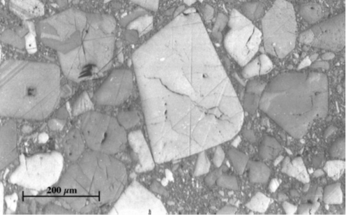
Figure 1. Scanning electron micrograph of polished fracture surface of HMX PBX 9501 (Rae et al, 2002)
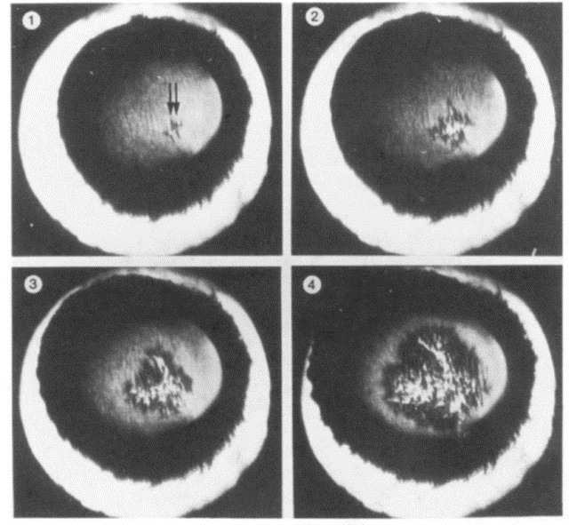
A concern with PBXs is that they can be subjected to various type of loadings such as accidental low velocity impact during transportation and handling or tool drop during manufacturing and machining (see Figure 2). Such occurances can lead to inadvertent ignition due to development of localized regions of high temperature known as "hot spots" at the microscale.[3] With the potential for inadvertent detonation associated with mechanical insult, the characterization of mechanical properties of PBXs has drawn large interest of the scientific community, and in particular of Dr. Gary Seidel research group in the Virginia Tech AOE Department, with regards to the safety and stability of these energetic materials.
In order to maintain the structural integrity of the energetic material and tolerate accidental external stimuli (e.g. someone dropping an ordinate or bumpy transport), crystal weight concentration ranges from 2 to 40% [1] and the corresponding volume fraction from 20 to 40% [2]. The surrounding polymer binder in PBXs have a range of properties such as low modulus-low strength-high ductility or relatively high modulus-high strength-more brittle behavior depending on the applications (that include mining and military such as detonators, solid rocket propellants and munitions). PBXs can be in the form of pressed or cast. Pressed PBXs are formed by consolidating binder coated crystals (molding powder) under vacuum and heat the mixture in a specific geometry which enables higher crystal weight concentration. On the other hand, this process induces crystal-crystal friction which can lead to crystal fracture. On the other hand, cast PBXs are processed by curing the crystal-binder mixture, having relatively lower crystal weight concentration with less filler particle-particle interactions. This process tends to make PBXs that are less sensitive to mechanical insult but can also result in void formation within the material.
An ideal PBX will usually have three components: the polymer that binds the explosives, the explosive or energetic material and an oxidizer which aids with the burning of the energetic material. In the scope of this experiment, the energetic material that would have been used is Ammonium Perchlorate (a common energetic for solid rocket propellants).
Due to concerns with safety, cost and availability, previous studies have used sugar as the crystal particles [2, 4], having a monoclinic crystalline make-up, similar to the actual explosive crystals. Sugar crystals are embedded in the same binder materials and using the same processing methods as actual explosives to produce mock energetic composites. Sivior et al. [2] studied mock energetics using 66% caster sugar crystals, with a mean particle size of ~270 μm embedded into HTPB binder using quasi-static loading and X-ray tomography (think of a CT scan) to investigate the key failure mechanism at room temperature. Recovered specimens from the quasi-static compression revealed the effects of debonding of sugar crystals from the binder with a color change due to increased number of scattering points developed during interfacial failure. X-ray tomography scans showed no obvious change in the sugar crystals shape or their size and no crystal fracture. On the other hand, debonding was taking place throughout the specimen which was supporting the observations from the quasi-static experiments. It was also found that interfacial failure between crystals and binder was the key failure mechanism during room temperature deformation. [5, 6]
The oxidizer component usually used in solid rocket propellants is an atomized aluminum powder (~3 microns size). The concentration of aluminum powder (by % weight) in the particulate mixture (which is energetic+oxidizer) directly affects the rate of combustion. Higher concentrations results in quick combustion or an explosion. Lower concentrations results in a uniform linear rate of combustion as desired in rocket propellants. For this experiment, the aluminum concentration with the particulate mixture is between 30% to 70% to ensure safety. Typically, a 80:20 ratio of energetic and oxidizer is the industry standard for a rocket propellant.
Another method to affect the combustion rate is to use what is called a bi-modal distribution. Statistically, bimodal distribution is defined as a data set with two modes. Think of it as a normal distribution bell curve but with 2 distinct mean peaks. Bimodal distributions, in this study, refer to a mixture of two different sizes of particles (if the particle sizes are measured and plotted, we will get two mean peaks, similar to the statistically defined bimodal distribution). These kind of particle distributions are very commonly used in the manufacturing of solid rocket propellants. The primary objective for doing this is to increase the rate of combustion. However, the increased bonding between the polymer and the particles due to increased effective surface area leading to higher van Der Waals forces, also affects the mechanical properties. For safety reasons, smaller size AP will not be used for fabrication. Instead, bimodal sugar distributions will be explored to understand the differences between the mechanical behavior of bimodal and single mode particle distributions.
Structural Health Monitoring using Carbon NanoTube (CNTs) Networks
As discussed previously, PBXs are highly volatile and sensitive to inadvertent damage and hence invoke the need for constant monitoring of their health.
A damaged PBXs may set off accidentally leading to mishaps, and may compromise operational success as well.
Currently adopted approaches to monitor health use a combination of externally mounted sensors such as strain gauges,
and periodic intrinsic inspections via X-rays or ultrasound. These approaches increase the complexity of on-board equipment,
increase downtime during inspection, and are generally not real time.
However, a novel approach to address these issues is being investigated by Dr. Seidel's research group at Virginia Tech.
This approach utilizes the multi-functional and piezoresistive properties of carbon nanotubes, an allotrope of carbon,
to create a network of sensing elements that are dispersed within the PBXs themselves thereby eliminating the need to mount external sensors.
Piezoresistance, an electro-mechanical interaction which results in change in electrical properties upon mechanical stimuli or vice-versa,
is exploited by using CNTs. A combination of complex physics such as quantum electron tunneling, in addition to the usual mechanisms
such as electrical changes due to geometric distortion (found in strain gauges) are responsible for CNTs acting as sensing elements.
A change in electrical properties, then suggests the existence of mechanical stimuli. By monitoring the change in the electrical properties of the PBX,
occurrences of damage can be detected in real time. The excellent mechanical properties of CNTs also result in mechanical property enhancement,
and hence CNTs have a multi-functional role. Thus, adding even small quantities of CNTs can result in real-time structural health monitoring while increasing the material performance.
In this experiment, to address safety concerns, students will not fabricate CNT doped PBX specimens.
However, Dr. Seidel's students will fabricate some batches and the raw, unprocessed test data will be made available to the students for analysis.
The data analysis conducted by the students will constitute a part of the statistical pool of data utilized by Dr. Seidel's group for their current, on-going research.
The focus of this lab will therefore to investigate the structural integrity of PBXs by submitting samples through a series of mechanical tests that will allow you to characterize the material properties as a function of crystal concentration. The properties to be measured are:
1.1 The Concept of Fracture Toughness
Ships, aircraft and rockets are extremely complex engineering systems with many thousands of components. In the construction of such systems it is impossible to completely avoid the presence of flaws such as cracks. Cracks are microscopic defects in a material that can grow catastrophically and lead to failure. Understanding the strength of materials in the presence of cracks is thus key to developing reliable aerospace and ocean engineering hardware. This experiment is designed to illustrate how strength in the presence of cracks - termed Fracture Toughness - is characterized and measured. This manual contains a detailed explanation of the procedure for determining fracture toughness of plastic materials.
Stress around a crack
Consider the idealized situation shown in Figure 3. This shows a uniform material of infinite extent that contains a semi-infinite
horizontal crack coincident with the negative x axis. The crack is
being pulled apart by a stress acting in the y direction, σy , that, far away from the crack, is uniform throughout the material.
The stress concentration in the vicinity of the crack may be determined analytically
if the crack tip is assumed to be sharp and the material is allowed to deform
only in a linear elastic fashion. Such an analysis shows that, along the
positive x axis,
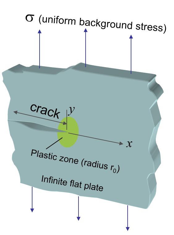
Figure 3. Infinite flat plate subject to uniform load in the presence of a crack
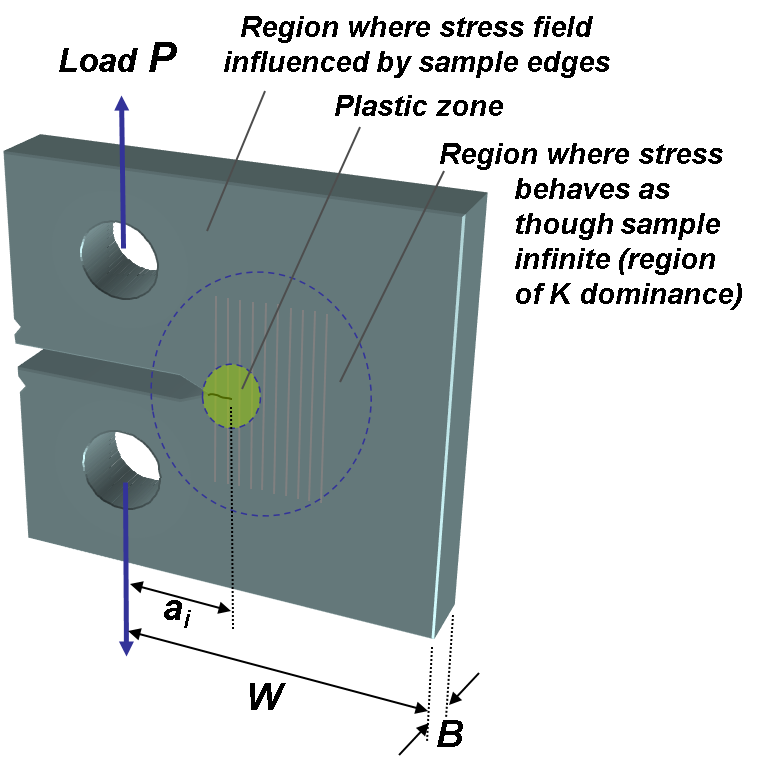
The real situation is of course more complicated. Consider the cracked material specimen in Figure 4. In the immediately vicinity of the crack the material does not behave in a linear elastic fashion and thus the large stresses predicted by LEFM and the above equation are not realized. In a metal, plastic yeilding occurs to relieve and redistribute the stress. In other materials, such as polymers or ceramics, different types of deformation, such as crazing or micro-cracking, may occur. For plastics, the material is usually so brittle that stress concentration within the specimen will result in rippling. The above equation is also unrealistic far from the crack where the shape of the specimen and the loading conditions determine the stress field. In between these regions, however, is a region where the crack dominates the stress field and the material deforms elastically. This is called the region of K dominance. Equation (1) is valid in this region.
Fracture and fracture toughness
Suppose the load on the specimen is increased until it breaks, i.e. fracture. The resistance to this fracture
may be characterized by the stress intensity at fracture, KIC, called the fracture toughness.
A KIC value represents a lower limiting value of the material's fracture toughness.
This value is used to estimate the relation between failure stress and defect size for a material in service where conditions of high tensile loading would be expected.
This experiment will involve the mechanical characterization of mock energetic composites. XTX (Extex) 8003/8004 are Class A explosives consisting of 80 wt% PETN or RDX coated with Sylgard 182 or Sylgard 184, a silicone rubber binder[7]. For obvious safety reasons, granulated sugar crystals will be used in place of actual crystals. Sylgard 184 PDMS was selected as a binder due to having faster curing time than Sylgard 182 but same chemistry. In order to obtain experimental investigation to assess the effect of mock crystal weight concentration on the mechanical properties of mock energetic composites under quasi-static and low velocity impact loading, 144 mock energetic composites with particulate weight concentrations ranging from 10 to 90% have been fabricated. 16 neat Sylgard 184 composites were also fabricated to provide a baseline measurement from which to assess the effect of mock crystal weight concentration on the mechanical properties. Each lab team has been assigned to test specific particulate weight concentration embedded into Sylgard 184 PDMS. Four specimens with a specific particulate wt% each for tensile, compression, compact tension and low velocity Charpy impact testing will be distributed to each team. In order to compare the results of mechanical testing and to ensure the consistency of the experiments, 4 teams are assigned to conduct the same particulate weight concentration. Therefore, 40 specimens will be tested each for tension, compression, compact tension and low velocity impact testing with a total 160 specimens in accordance with ASTM D638, ASTM D695, ASTM D5045 and ASTM D6110.
Special Consideration for this experiment under COVID operational guidelines
Due to COVID restrictions, it will not be possible this semester for students to fabricate and test their own samples (as is typically done).
Instead, Dr. Seidel's research group will provide live demos of the experiment to each lab session, and then provide the raw unprocessed data to you for analysis as part
of a homework assignment. Sections 3-5 (along with Appendix 4) are to provide you with a sense of how the experiment is setup and performed, and written to guide students accordingly.
You will receive specific instructions on how to process the data as part of your homework assignment.
To perform the tensile, compression, and compact tension testing an ADMET eXpert 7600 Universal Testing Machine will be used and is shown in Figure 5. It is connected to a computer running an MTESTQuattro program. The computer is used to log the test data and has direct control over the movement of the machine through manual control access. Control of the machine will be carried out by the predetermined testing procedure for this experiment. The machine has a crosshead - a horizontal bar - that can be accurately traversed up and down by means of internally housed jack screws.
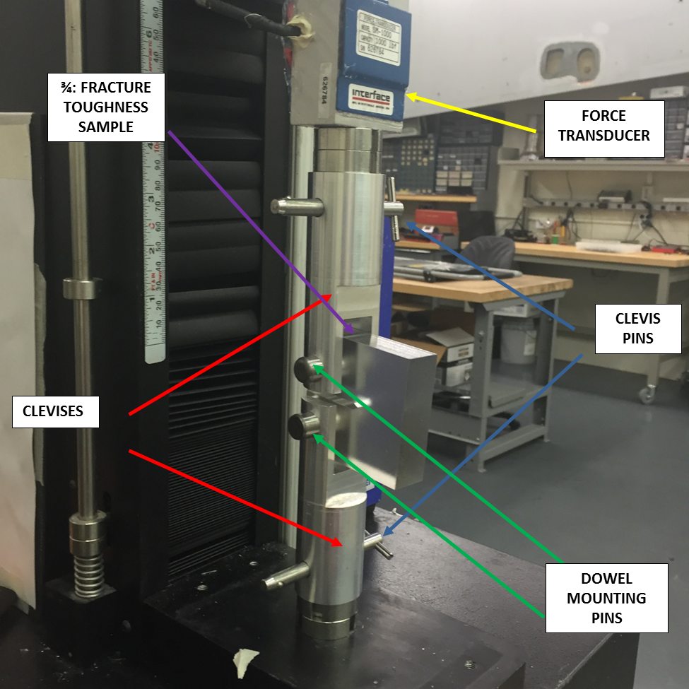
Specimens are tested by attaching them between the crosshead and the stationary base of the machine using the mounting dowel pins and clevis, and then running the compact tension procedure for this experiment. The load on the sample is recorded by an Interface Model SM-100-38 force transducer mounted between the sample and the crosshead. This force transducer is shown in Figure 3. The range of the load cell output goes from 0-100 lbf. This load cell has been calibrated and features a rated accuracy of 0.25% F.S. .
The testing machine is a potentially dangerous device and should be treated with great respect. A specially trained operator will be on hand (either your TA or a faculty member) to oversee operation of the machine and give you safety advice. There is an emergency stop button. If you are not told, ask where it is. Do not touch any other controls on the machine without express instructions from the operator.
To remove any load and position bias due to specimen mounting, you will zero the displacement and load readings after mounting the sample and before testing. This will make certain your load and displacement data start from their respective origin.
Mock Energetics Specimen
Fabricating all the specimen for this experiment is an intricate process. You will be in charge of fabricating your own specimen. A detailed procedure is provided in Section 4. While great care will be taken to coat the sugar crystal with PDMS, sedimentation of the crystals at the bottom of the mold inevitably occures during the curing process. This will obviously create non-uniformities in the material of the samples and needs to be both documented and discussed. The sedimentation layer thickness will need to be measured for all samples with sugar weight concentration up to 60%. The document below (that provides the geometric details of each sample type) highlights how these measurements should be taken. Here are the details behind the dimensions of each test sample:
You will be given specific instructions on how to use the computer and software in the procedure section of this manual.
Don't forget to make a complete list of the apparatus and instrumentation you are using for your notes.
Mock Energetics Specimen
Each team will be testing specimen that have 3 possible compositions:
This entire section should be read thoroughly as part of your preparation and before embarking on the experiment.
Dr. Gary Seidel's research group has prepared a batch of samples for the entire class. If you are interested in
learning how these specimen are fabricated, the document below describes this process in details:
Mechanical Characterization
Unlike the other experiments in AOE 3054 this experiment has a very specific procedure to ensure safety and agreement with the requirements of the ASTM standards. To meet these standards, the parameters for the 4 types of testing have been set as follows:
Tensile Testing
Tensile testing will be conducted in accordance with ASTM D638 at constant crosshead displacement rate of:
You will notice that same strain rate is used for both tension and compression experiments so that the modulus of elasticity under tensile vs compressive at quasi-static loading can be directly compared.
Compact Tension TestingTensile, Compression, and Compact Tension Testing Procedures
You should also refer to the ADMET Testing Procedures" PDF below that details the proper steps for safely operating the test machine using MTESTQuattro for the tensile, compression, and compact tension tests.
This will help you identify where information is output and how to export the raw data after you run the test .
Impact Resistance Testing Procedures
Details for the impact resistance testing are provided in Appendix 4.